
The idea
I turned three pages of messy pencil sketches into a clean, IKEA-style assembly plan for a nest box with a built-in camera, in one prompt.
The plan was simple: a classic box for tits and other cavity nesters, plus a small compartment under the roof where a camera looks down at the nest. I had drawn it on paper over a couple of evenings. The sketches had parts, a few dimensions, a sum of heights and some question marks. They were good enough for me, and useless for anyone else.
So I dropped the three phone photos into a folder and asked Claude Code: “Try to read the hand-written plan to build a bird house. Can you create an IKEA-like plan how to build one?”
The input: three photos of paper
The whole input was three phone photos, one of them upside down, all in German shorthand.
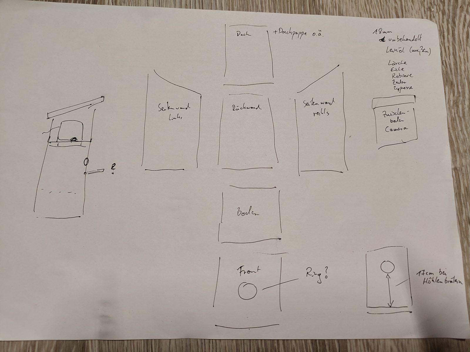
Sheet 1: the exploded view. Roof (Dach) with roofing felt, two side walls, back, floor (Boden), front with the entrance hole and a “Ring?” note, and a separate camera floor (Zwischenboden Camera). Top right: 18 mm, untreated, linseed oil outside, and a list of woods (larch, oak, robinia, cedar, cypress). Bottom right: “17 cm bei Höhlenbrütern”, the hole height for cavity nesters.
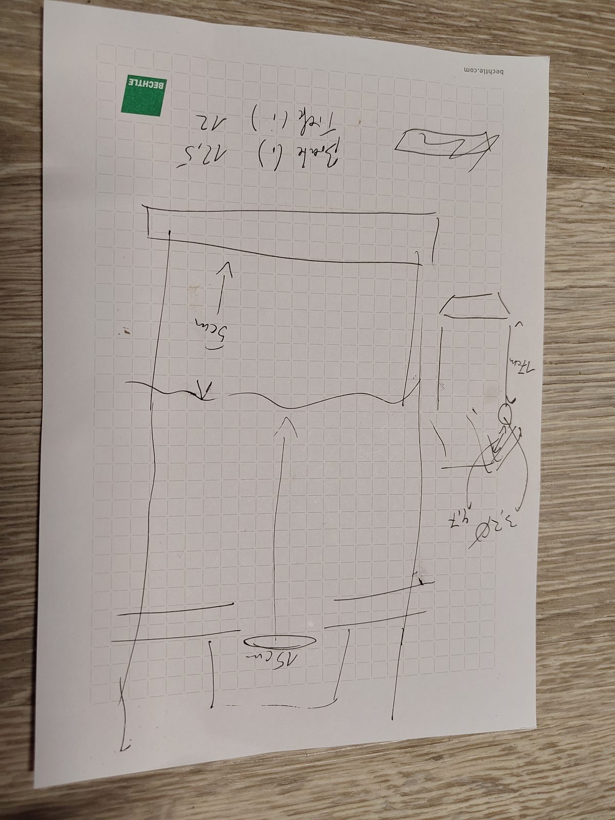
Sheet 2: the cross-section, photographed upside down. Inside width 12.5, inside depth 12, the nest about 5 cm high, the camera lens 15 cm above it, the 17 cm hole height and a hole diameter of 3.2 next to a “4.7”.
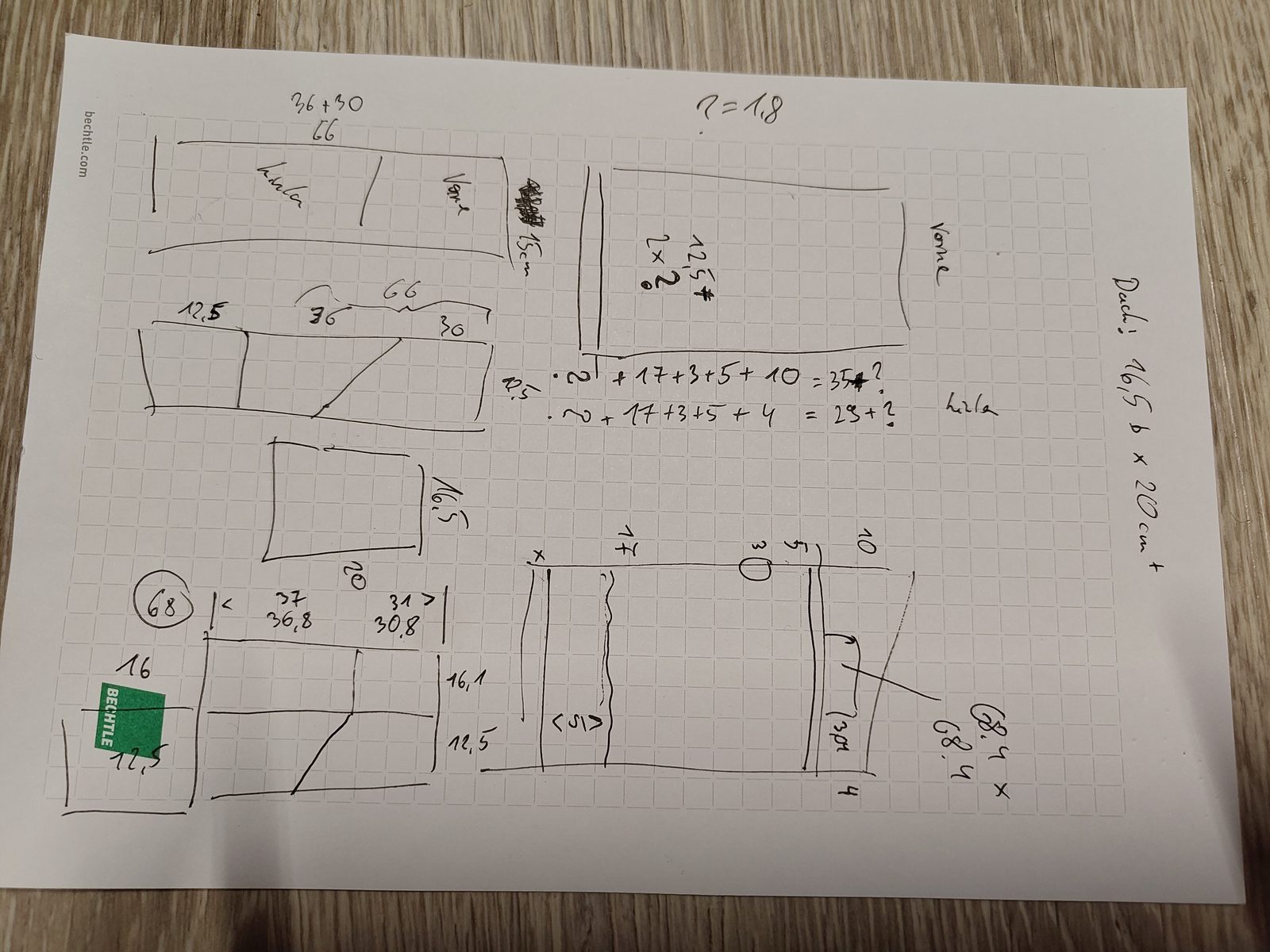
Sheet 3: the maths. Board thickness “? = 1.8”, a cutting layout with 36.8 / 30.8 and a diagonal cut, 16.1 and 12.5 strip widths, the roof at 16.5 × 20 cm, and two sums for the front and back heights that end in question marks.
What Claude read from the scribbles
Claude decoded almost everything correctly, including the upside-down page, and cracked the height sum I had left with question marks.
| Sketch says | Claude’s reading |
|---|---|
| ? = 1.8 | 18 mm boards, untreated inside, linseed oil outside |
| Breite (i) 12.5 | Inside width 12.5 cm |
| 16.1 strip | Front and back cover the side edges: 12.5 + 2 × 1.8 = 16.1 cm |
| · + 17 + 3 + 5 + 4 = 29 + ? | Front: floor 1.8 + 17 to the hole + 3 hole + 5 gap + 4 camera room = 30.8 cm |
| · + 17 + 3 + 5 + 10 = 35 + ? | Back: the same with 10 cm camera room = 36.8 cm |
| 36.8 / 30.8 with a diagonal line | Both side walls from one 12.5 × 68.4 cm strip with one diagonal cut |
| Dach 16.5 × 20 | Roof 16.5 × 20 cm plus roofing felt |
| Ø 3.2, 4.7 | Entrance hole Ø 32 mm; 4.7 read as the outer diameter of the guard ring |
The nice part is the missing term in my sums. I had written the heights as “35 + ?” and “29 + ?”. Claude filled in the 1.8 cm floor and got exactly the 30.8 and 36.8 that were already on my cutting sketch.
What Claude fixed and added
Claude also found a real flaw in my design: with the roof resting on the sloped side walls, the top of the front panel would have hit the roof.
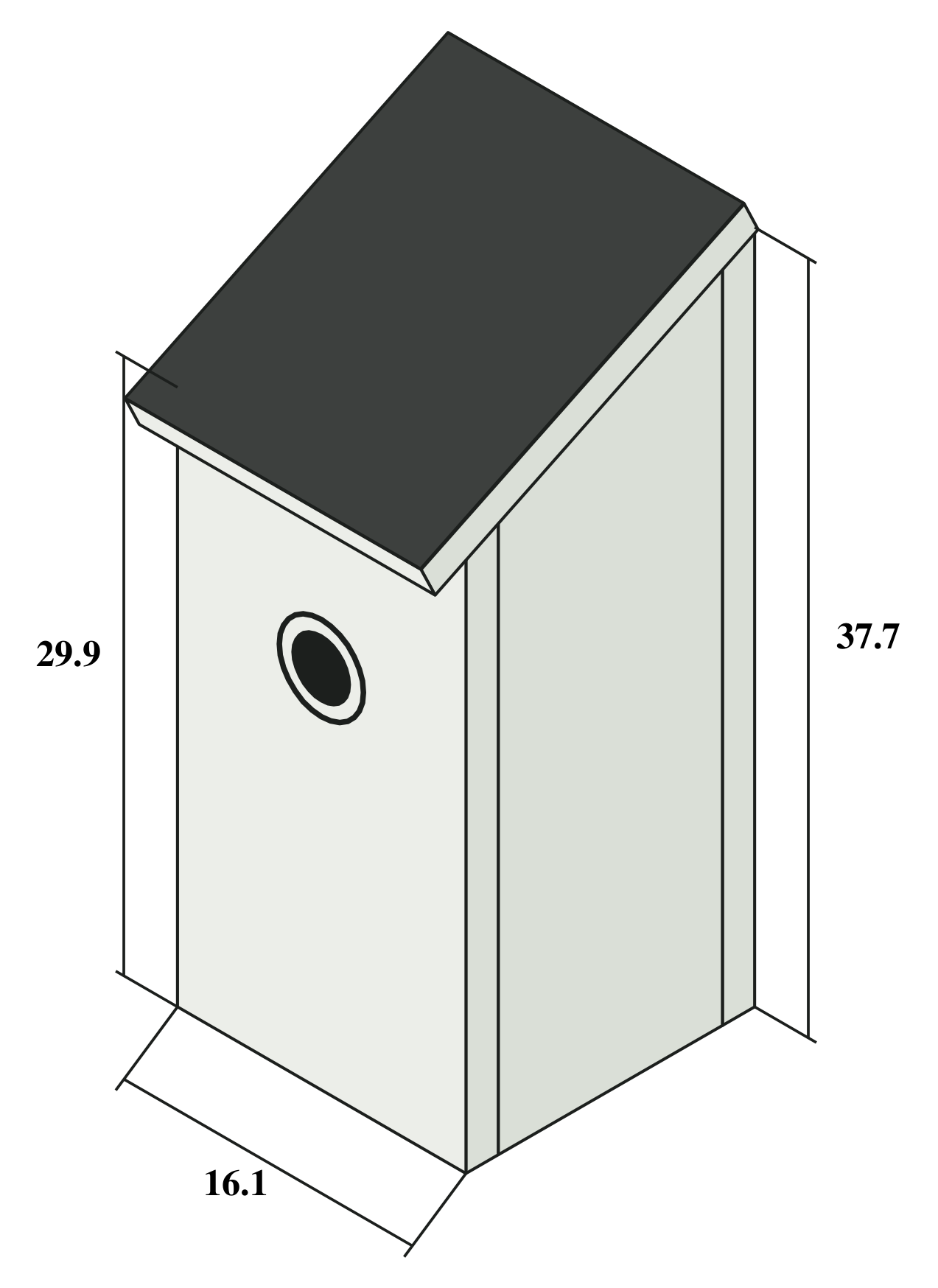
- 26° bevel on front and back. The slope is 6 cm over 12.5 cm, about 25.6°. The front’s outer face must end at 29.9 cm, so both top edges get a bevel. The back grows to 37.7 cm. Without a bevel saw: cut the front to 29.9 and the back to 36.8 and accept small air gaps.
- Guard ring kept, perch dropped. My “Ring?” became a predator guard. My perch with a “?” was left out, because it helps cats and martens more than the birds.
- Cleaning without tools in the nest. Front and roof are only screwed, never glued. Once a year: unscrew the roof, lift out the camera floor, empty the nest. The camera cable needs slack for that.
- Small things I had forgotten. Four Ø 6 mm drainage holes in the floor, grooves inside the front so fledglings can climb out, a lens hole in the camera floor, a sealed cable hole in the back and two cleats to carry the camera floor at 25 cm above the floor.
- A cutting plan. Everything fits on one 1.8 × 30 × 100 cm board, ripped into a 16.5 cm and a 12.5 cm strip.
The output: a real assembly manual
The result reads like a flat-pack manual: line drawings, part letters, screw counts and very few words. Here is the complete plan as Claude produced it. It is also available as an 8-page PDF.
Camera Nest Box
A nest box for tits and other cavity nesters with a separate camera compartment under the roof, built from one 18 mm board: inside 12.5 × 12.5 cm, entrance Ø 32 mm, 37.7 cm tall. Untreated inside, linseed oil outside.
Tools: saw (bevel cut 26°), drill, Ø 32 mm Forstner bit or hole saw, Ø 6 mm drill bit, screwdriver, pencil, ruler.
Parts
All sizes in cm, board thickness 1.8.
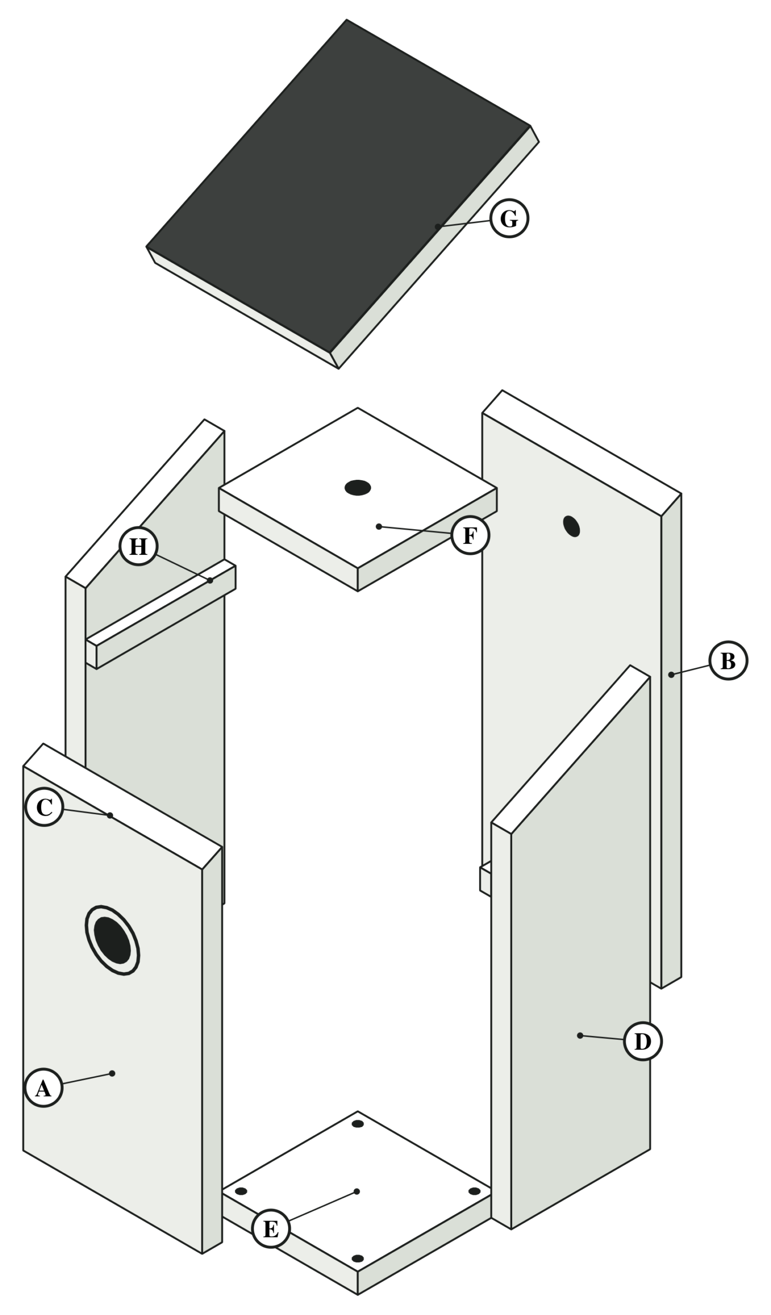
| Part | Name | Qty | Size (w × h, cm) |
|---|---|---|---|
| A | Front (Front), top edge bevelled 26° | 1 | 16.1 × 30.8 |
| B | Back (Rückwand), top edge bevelled 26° | 1 | 16.1 × 37.7 |
| C | Side left (Seitenwand links) | 1 | 12.5 deep · 36.8 back / 30.8 front |
| D | Side right (Seitenwand rechts) | 1 | same as C |
| E | Floor (Boden) | 1 | 12.5 × 12.5 |
| F | Camera floor (Zwischenboden) | 1 | 12.5 × 12.5 |
| G | Roof (Dach), plus roofing felt | 1 | 16.5 × 20 |
| H | Cleat (Auflageleiste) | 2 | 1.0 × 1.8 × 12.5 |
Hardware
Stainless steel, since the box lives outdoors.
| Qty | Item |
|---|---|
| 20 | Wood screw 4 × 40 |
| 4 | Wood screw 3 × 20 |
| 1 | Entrance guard ring, Ø 32 mm inside |
| 1 | Roofing felt, about 20 × 24 cm, plus 8 staples |
| 1 | Raw linseed oil, outside only |
Cutting plan
Everything comes from one 1.8 × 30 × 100 cm board, assuming a 3 mm saw blade.
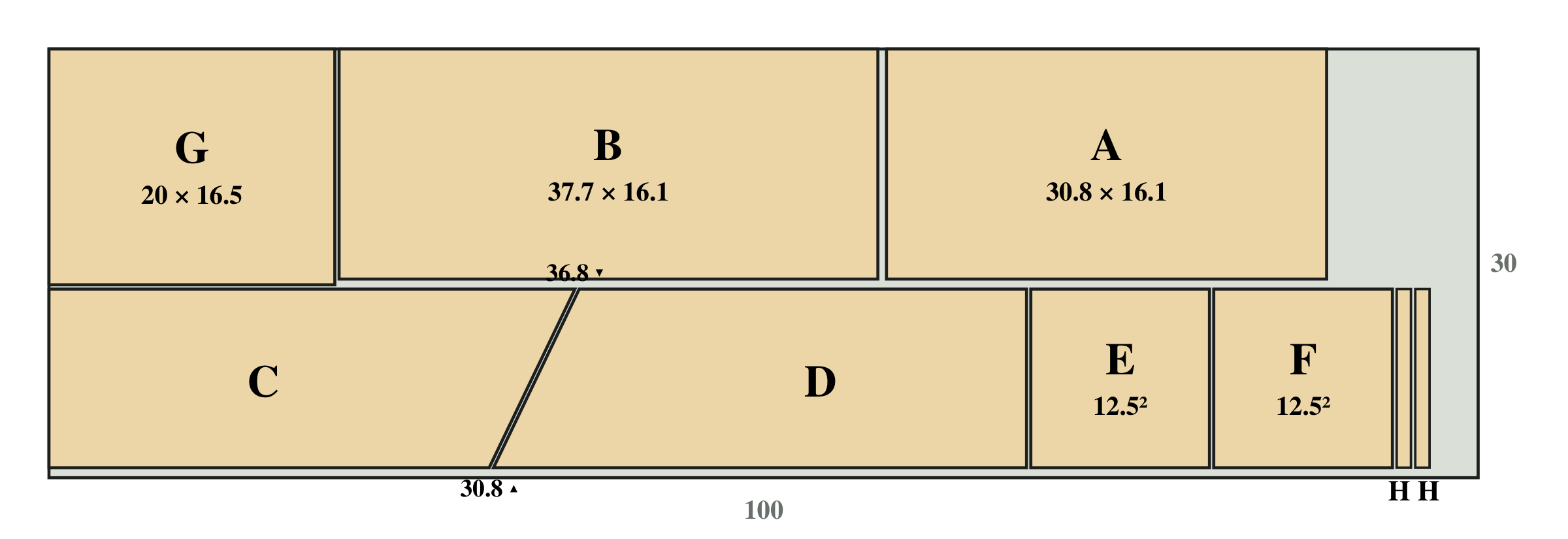
- Rip the board into a 16.5 cm strip and a 12.5 cm strip.
- Cut G, B and A from the wide strip, then trim A and B to 16.1 cm wide.
- For C and D: on the 68.4 cm piece, mark 36.8 on one long edge and 30.8 on the other, both from the same end. Saw along the diagonal.
- Lay the two sides on top of each other and trim the longer one at its square end.
- Rip the two cleats H from the offcut.
Assembly
Screws only, no glue on A and G.
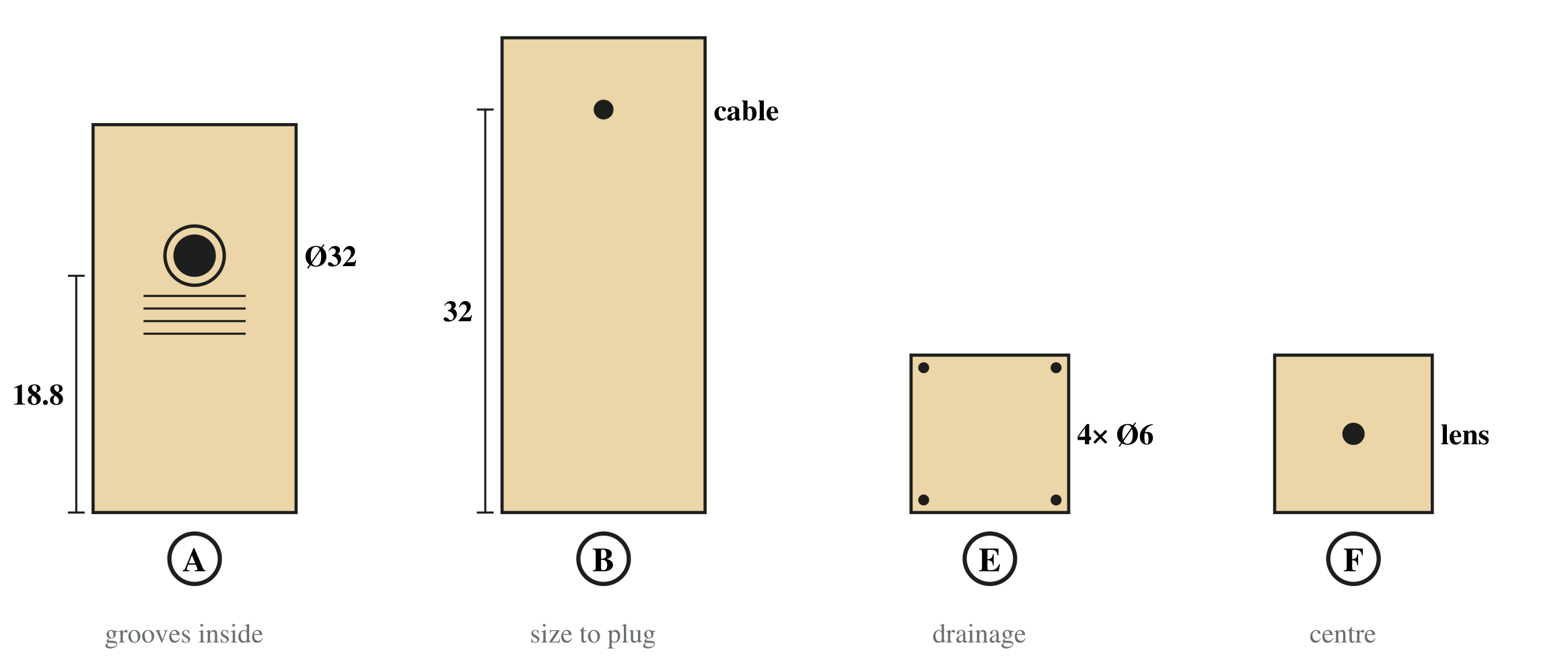
Step 1: Drill. Entrance hole in A, cable hole in B, drainage in E, lens hole in F. Saw 3–4 grooves into the inside of A below the hole so the young birds can climb out. The hole sits 17 cm above the floor surface. Size the lens hole to your camera.
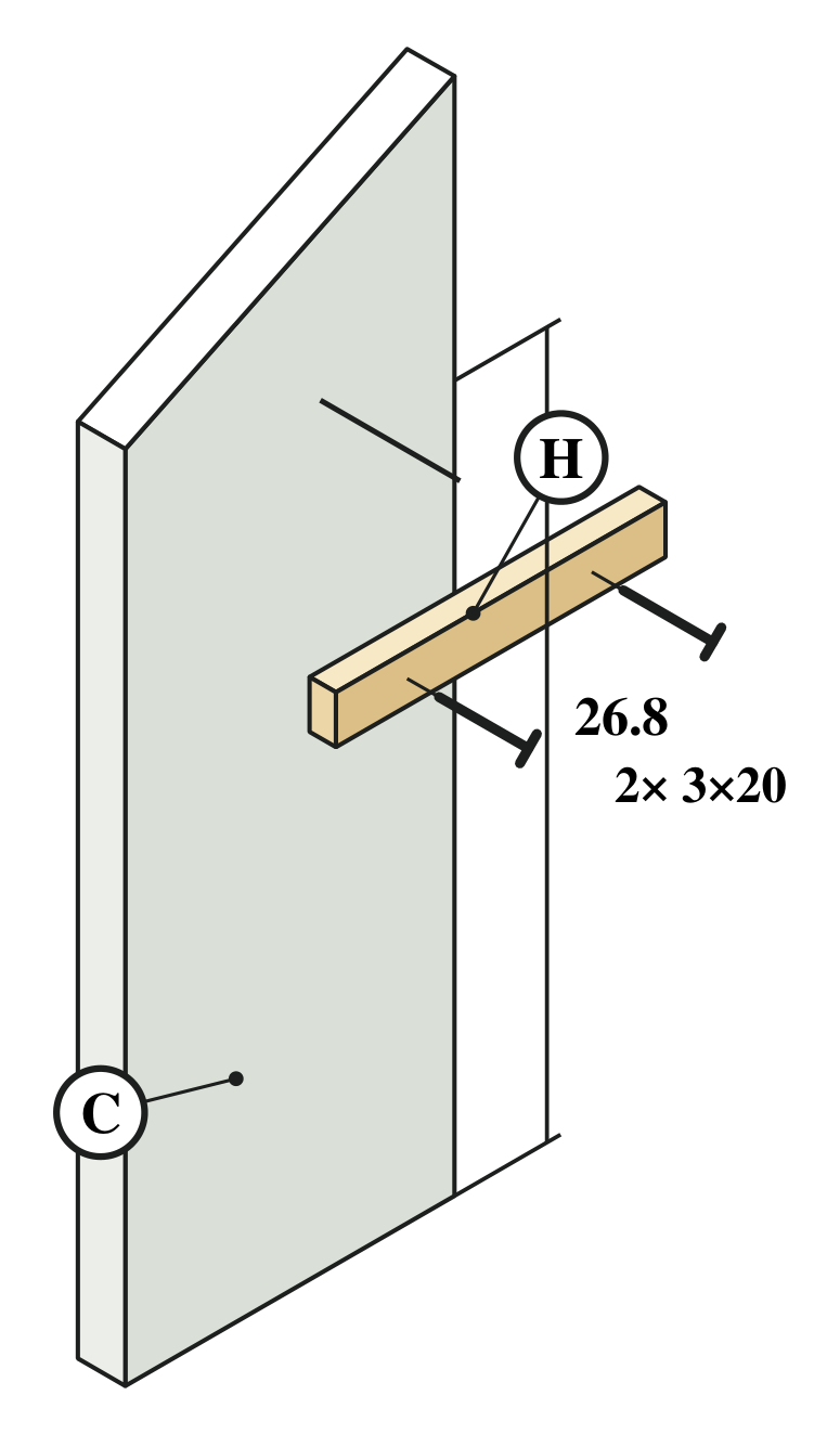
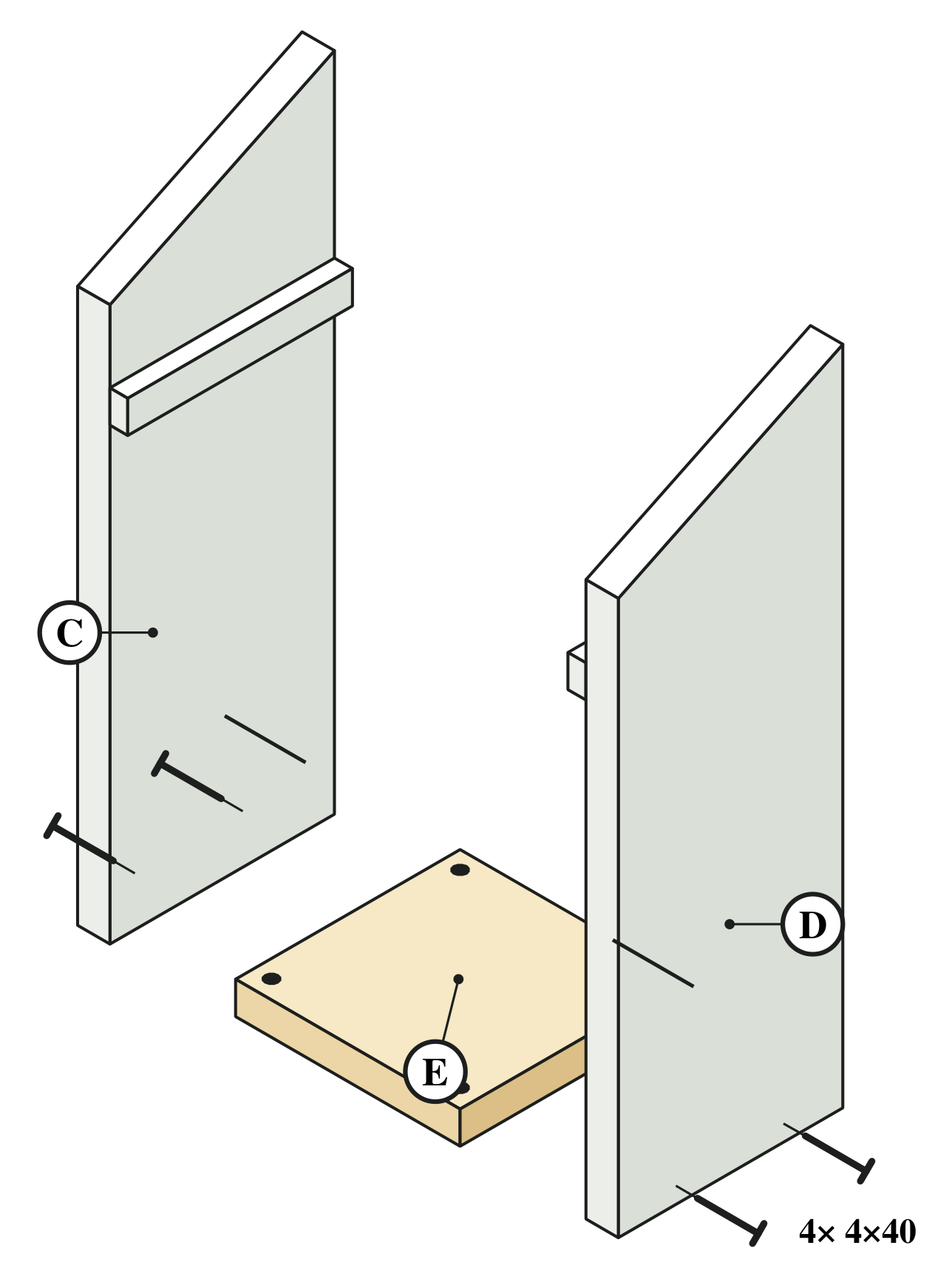
Step 2: Cleats. Screw one cleat H to the inside of each side wall, top edge 26.8 cm above the bottom edge. D is the mirror image of C.
Step 3: Floor. Put the floor E between C and D, flush with the bottom edges. Two screws per side. Pre-drill Ø 3 mm so the edges don’t split.
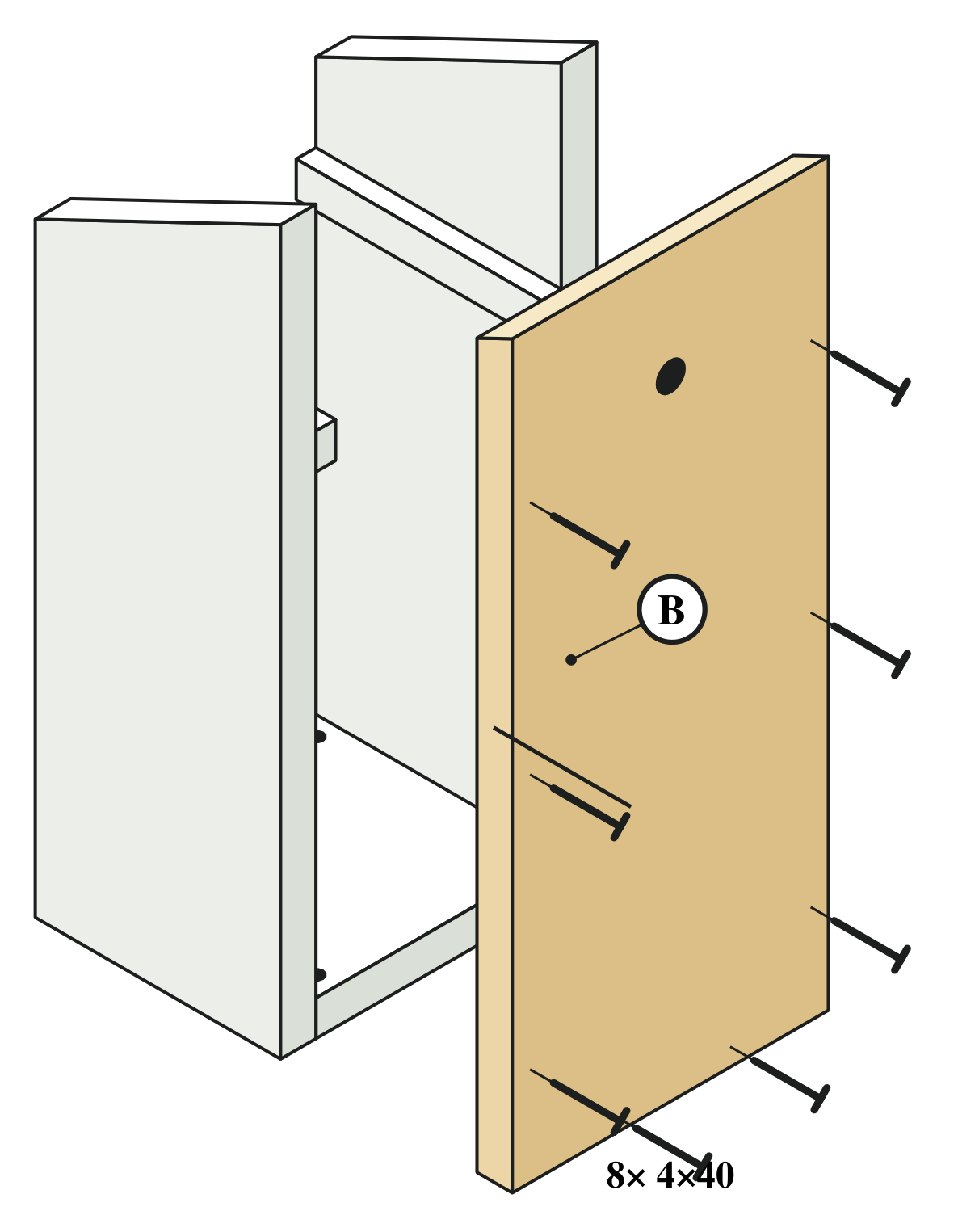
Step 4: Back. Screw the back B on from behind: three screws into each side wall, two into the floor. The bevel on B slopes the same way as the side walls.
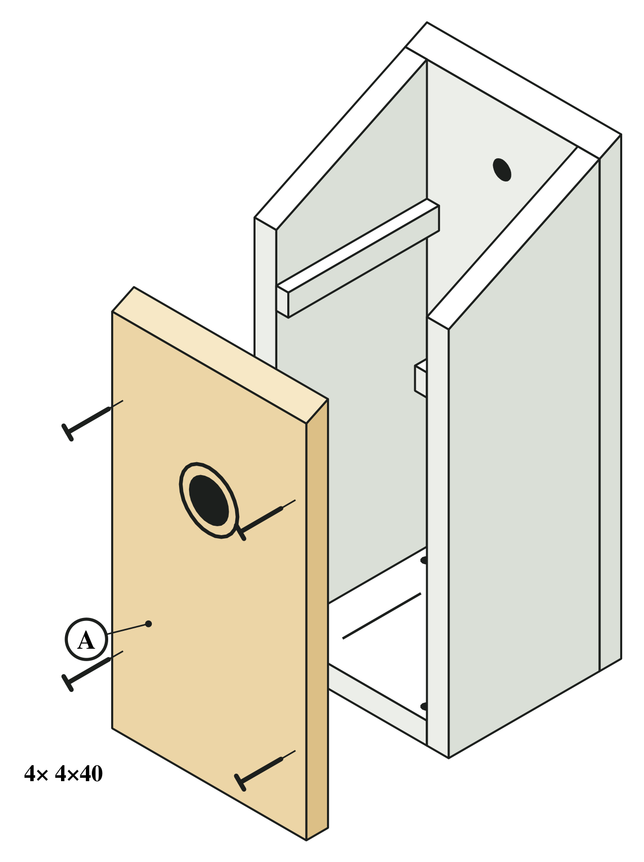
Step 5: Front. Screw on the front A, two screws per side, no glue, so you can take it off again. Mount the guard ring over the entrance hole.
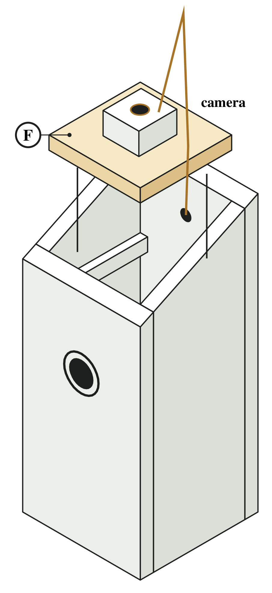
Step 6: Camera floor. Fix the camera to F above the lens hole. Lay F on the cleats and run the cable out through B. Leave slack so F can be lifted out for cleaning, and seal the cable hole.
Step 7: Roof. Staple the roofing felt onto G and fold it over the edges. Put G on flush with the back and screw it into C and D. The roof overhangs the front by about 2 cm.
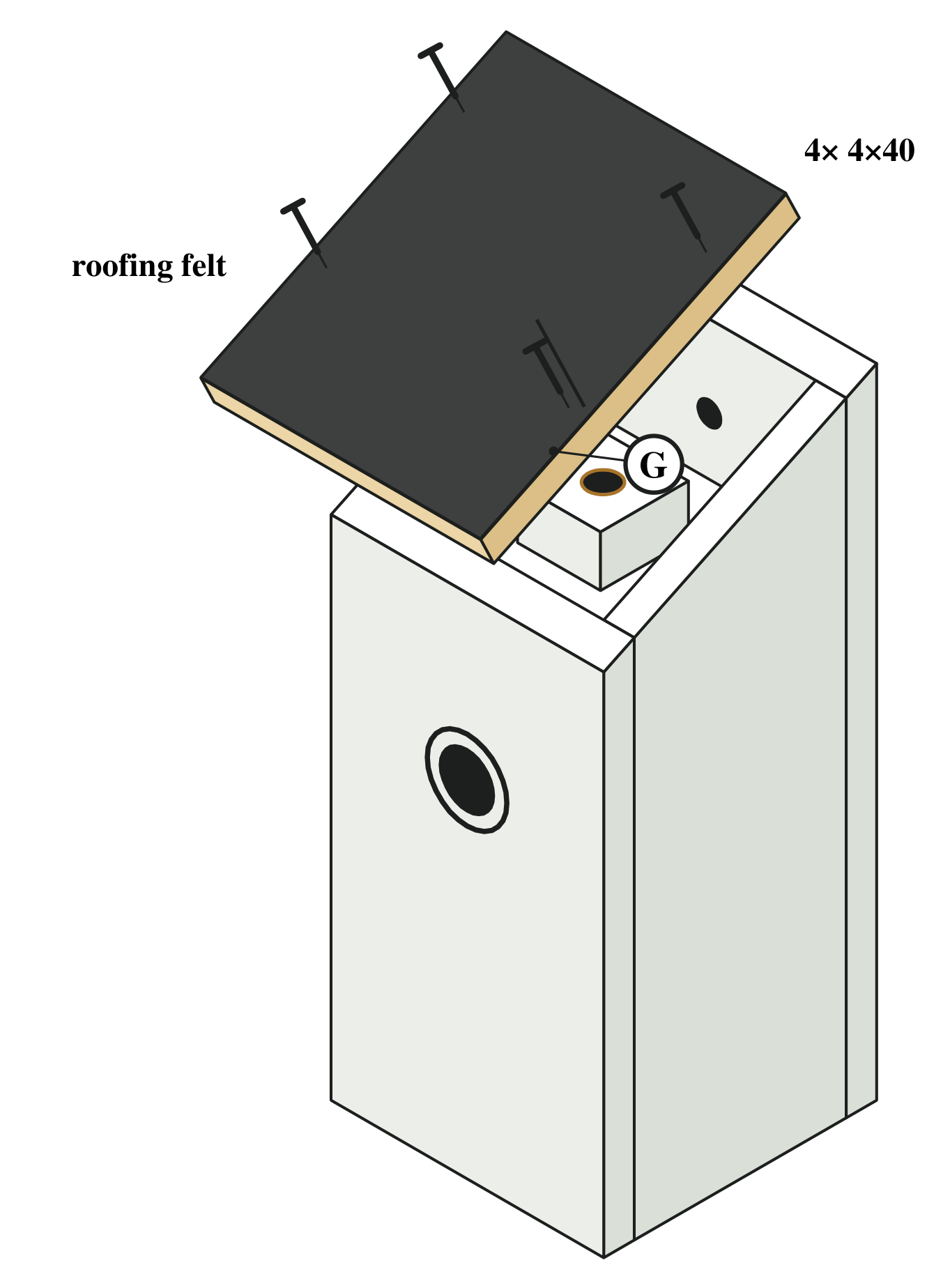
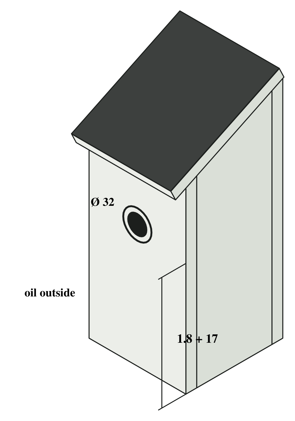
Step 8: Finish. Oil the outside with linseed oil and leave the inside untreated. Hang the box 2–3 m high with the entrance facing east or south-east. Clean it once a year in autumn: unscrew G, lift out F, empty the old nest.
Do and don’t
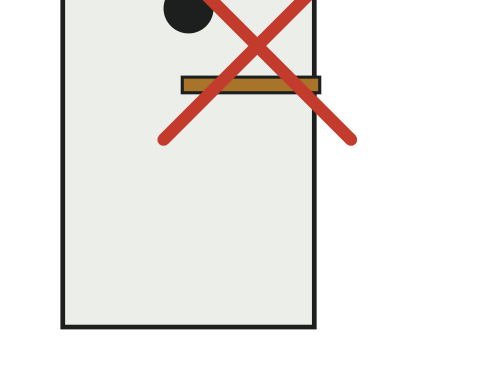
- No perch. A perch under the entrance helps cats, martens and magpies more than the birds.
- No oil, paint or glue inside. Fumes and residue harm the brood.
- Hole size. Ø 32 mm suits great tits, nuthatches and sparrows. Use Ø 26–28 mm if you only want blue tits.
- Weather. Hang it out of the main wind and rain direction, tilted slightly forward rather than back.
How the drawings were made
There is no CAD file behind the plan. Claude described every panel as a 3D shape in centimetres and wrote a small JavaScript function that draws them as isometric line art (SVG) inside the plan’s HTML page.
- Each part is a flat outline pushed out by its thickness, 1.8 cm. The side walls are trapezoids, and the roof sits on the 25.6° slope.
- The script projects the 3D points onto the page, hides the faces that point away from the viewer and draws the nearer parts last.
- Exploded views just move parts apart along an axis. Arrows, screws, part letters and dimension lines are placed in 3D and projected the same way.
- Step 4 uses a second view from behind, so you can see the screws going into the back.
- New parts in each step are tinted in a wood colour, the rest stays grey.
Because the drawings come from the same numbers as the cut list, the pictures and the measurements always agree. Changing one dimension in the script would redraw every step.
One caveat: Claude had no browser in its sandbox, so it placed the labels blind at first. It saw the drawings for the first time when it rendered them to PNG for this post.
Building the images and the PDF yourself
The images in this post and the 8-page PDF are built from the plan page with two small scripts, without a browser. Node runs the drawing code and writes SVG files; PyMuPDF turns them into PNGs and lays out the PDF.
You need Node.js and Python 3:
python3 -m venv venv
venv/bin/pip install pymupdf

# 1) run the drawing code of the plan page, write one SVG per drawing
node export_svgs.js plan.html out/svg

# 2) SVG -> PNG (150 dpi) and the multi-page A4 PDF
venv/bin/python build_assets.py out/svg out
#    -> out/png/*.png, out/camera-nest-box.pdf
Step 1: drawings as SVG
The plan page draws its pictures with a script that writes SVG markup into placeholder elements. export_svgs.js runs that same script in Node with a fake document that just collects the markup. It then makes each drawing standalone: the theme colours (CSS variables) are replaced with the light-mode values, a white background is added, and the four small panels of step 1 are combined into one picture.
const src = fs.readFileSync(html, 'utf8');
const script = src.slice(src.indexOf('<script>') + 8, src.lastIndexOf('</script>'));
const els = {};
global.document = { getElementById: id => (els[id] = { set innerHTML(v) { this.v = v; } }) };
new Function(script)();          // every drawing now sits in els[id].v

const fix = s => s.replace(/var\(--([a-z-]+)\)/g, (m, n) => vars[n]);  // theme colours -> fixed colours
for (const [id, el] of Object.entries(els))
  fs.writeFileSync(`${outDir}/${id.replace(/^d-/, '')}.svg`, single(el.v));
One pitfall: MuPDF ignores the x/y position of SVG elements nested inside another SVG, so all four panels landed on top of each other. Wrapping each panel in <g transform="translate(x,y)"> fixed it.
Step 2: PNG images
PyMuPDF opens an SVG like a one-page document, so rasterising is two lines:
for svg in sorted(SVG_DIR.glob("*.svg")):
    pix = pymupdf.open(svg)[0].get_pixmap(dpi=150)
    pix.save(PNG_DIR / f"{svg.stem}.png")
Step 3: the multi-page PDF, as vector graphics
The PDF is laid out with PyMuPDF’s Story, which places HTML and CSS on pages. Each manual sheet (cover, parts, hardware and cutting plan, four assembly pages, do and don’t) is its own small HTML snippet and starts on a new A4 page.
My first version simply put the PNGs into the HTML. That produced a 76 MB PDF, because the 150 dpi images ended up in the file uncompressed. Far too big for the media library, and pointless, since the drawings are vectors to begin with. The fix keeps them as vectors: the HTML only reserves an empty box of the right size for each drawing, Story reports where each box landed, and afterwards the SVG, converted to a one-page PDF, is stamped into that box. The PDF shrank to 483 KB and stays sharp at any zoom.
VECTOR = {svg.stem: pymupdf.open("pdf", pymupdf.open(svg).convert_to_pdf()) for svg in SVG_DIR.glob("*.svg")}

def img(name, height):                    # reserve a box for a drawing
    r = VECTOR[name][0].rect
    width = min(515, height * r.width / r.height)
    WIDTHS[name] = width
    return f'<div id="img-{name}" style="height:{width * r.height / r.width:.1f}px"></div>'

boxes, pageno = [], 0
writer = pymupdf.DocumentWriter("out/camera-nest-box.pdf")
for html in PAGES:                        # one HTML snippet per sheet
    story = pymupdf.Story(html=html, user_css=CSS)
    more = True
    while more:
        dev = writer.begin_page(A4)
        more, _ = story.place(FRAME)
        story.element_positions(          # where did the reserved boxes land?
            lambda pos: boxes.append((pos.pageno, pos.id[4:], pos.rect))
            if (pos.id or "").startswith("img-") and pos.open_close & 1 else None,
            {"pageno": pageno})
        story.draw(dev)
        writer.end_page()
        pageno += 1
writer.close()

doc = pymupdf.open("out/camera-nest-box.pdf")
for pno, name, rect in boxes:             # stamp the vector drawings into the boxes
    rect = pymupdf.Rect(rect)
    w = WIDTHS[name]
    x0 = FRAME.x0 + (FRAME.width - w) / 2
    doc[pno].show_pdf_page(pymupdf.Rect(x0, rect.y0, x0 + w, rect.y1), VECTOR[name], 0)
doc.save("camera-nest-box-final.pdf", garbage=4, deflate=True)
Two things to watch. Story never splits a block, so a drawing that is too tall simply runs off the bottom of the page; the script therefore checks every box against the page margin and stops with an error. And MuPDF uses its own built-in fonts, so the labels inside the drawings come out in a serif face. That’s cosmetic.
What I take away
The surprising part was not the drawing but the reading: Claude worked out what my half-finished sums meant and caught a design flaw I had missed.
It also kept a clear line between what it read and what it decided. Every assumption, like the 4.7 next to the hole or dropping the perch, is listed on the plan itself, so I can disagree with it.
Next up: buying a board, building the box before the breeding season and choosing a camera that fits into 8 cm of headroom. I’ll post an update when the first tit moves in.
After the article: getting it onto the blog
The first draft of this article was finished quickly. Getting it onto this blog with real images and a downloadable PDF took longer than writing it, and most of the snags were about tools, not content. Here is what happened after the draft, in order.
- Screenshots: no browser. I asked for screenshots of the plan page. Claude downloaded a headless Chromium, but it needed system libraries that can only be installed as root, which the sandbox doesn’t allow. Instead, Claude exported the drawings themselves as SVG and placed them in the draft.
- WordPress draft, after a permission check. When my blog’s MCP server appeared in the session and I only typed “Continue”, Claude’s first call to WordPress was blocked by Claude Code’s auto mode, because I had not explicitly asked for anything to be written to the blog. Claude prepared the post locally and asked. After I said “create the WordPress post (draft only, full width template)”, it created the draft and set the theme’s full-width template via the
_wp_page_templatemeta field, which it looked up on one of my existing posts. - Images and PDF without a browser. Claude wrote the two build scripts described above: Node runs the plan’s drawing code and writes SVGs, PyMuPDF renders PNGs and an 8-page A4 PDF. This was also the first time Claude actually saw its drawings, after placing every label blind. Step 1 needed a fix because MuPDF ignores the position of nested SVG elements.
- Privacy check on the photos. Before uploading, I asked for the metadata to be removed. The phone photos contained the exact GPS position where they were taken and the phone model. Claude wrote fresh copies without any metadata, scaled to 1600 px (150–230 KB each instead of 2.3–2.9 MB), and checked them afterwards. It also replaced the original photos it had uploaded to its own private draft earlier and deleted them there.
- Uploads: the tool couldn’t do it. The WordPress MCP plugin on this blog only offers an image upload that fetches from a public URL. Claude tested a data URL and a real base64-encoded PNG; both were rejected. A
media/upload-base64ability exists in a different plugin, which isn’t installed here. So I uploaded the files myself through the media library, and Claude replaced every placeholder with a proper image, caption and alt text. - A 76 MB PDF. The media library refused the PDF. The PNGs had been embedded uncompressed. Since the drawings are vectors to begin with, Claude changed the script to stamp the SVGs into the pages as vector graphics. The PDF went down to 483 KB. Three drawings then ran off the page, so the script now sizes drawings by height and stops with an error if one doesn’t fit.
- Download link and media metadata. After I uploaded the new PDF, Claude checked it was the right file by comparing its size byte for byte, added the download link, and filled in title, caption, description and alt text for all drawings and the PDF in the media library.
Every step that wrote to the blog was confirmed by reading the result back, and the post stayed a draft throughout.
What it cost
The whole job, from reading the sketches to the media metadata, would have cost about $11 at Claude API prices. The numbers are the real token counts from the Claude Code session log: 122 API calls to Claude Opus 5.5 over about 2 hours 10 minutes.
| Token type | Tokens | Price per million | Cost |
|---|---|---|---|
| Input, uncached | 244 | $4.00 | $0.00 |
| Output (including thinking) | 141,328 | $20.00 | $2.83 |
| Cache writes (1-hour cache) | 417,687 | $8.00 | $3.34 |
| Cache reads | 24,475,670 | $0.20 | $4.90 |
| Total | ≈ 25.0 M | ≈ $11.07 |
- Most tokens are re-reads. Every call sends the whole conversation again, including the three sketch photos, all tool results and the long post HTML. That’s why 24.5 of the 25 million tokens are cache reads. Without prompt caching, they would cost the full $4 per million, and the bill would be about $100 instead of $11.
- Output is small but expensive. 141,000 tokens of output and thinking make up about a quarter of the cost. The biggest pieces were the plan page, the post HTML and the build scripts.
- One assumption. The session used the 1-hour prompt cache, priced here at twice the input rate ($8 per million). The other rates are the list prices for Claude Opus 5.5: $4 input, $20 output and $0.20 cache reads per million tokens.
Not included: the last few requests that added these two chapters, and anything outside the Claude API. On a Claude subscription, the same work counts against usage limits instead of being billed per token.